Industrial Control Panel (ICP)
Create a new ICP
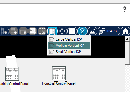
The physical mode toolbar has a button for adding an ICP to the workspace.

Clicking this button and selecting one of the available predefined ICP sizes from the pop-up menu will place a new Control Panel on the workspace. After this, you can enter the ICP as you would a Wiring Closet by clicking on it.
ICP Structure
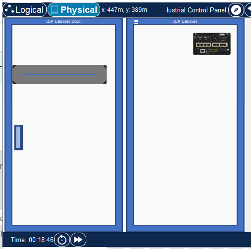
This container initially shows its sub-containers: the door (left side) and the cabinet (right side). The door is initially open, but it can be closed and re-opened by clicking on its rectangular handle. When the door is open, any devices shown on it will be rendered in their “back-side” view.
Putting items into the ICP
Items can be added to the ICP in the same way we add them to wiring closet containers (e.g., racks). At this point, there are no restrictions as to what devices can be placed within it.
Moving items between the cabinet and the door
Items can be moved around the ICP by dragging them with a mouse, as we do on PT workspaces. Dragging an item with the Shift key pressed and held down (Shift+Drag) allows you to move items from the door to the cabinet and vice versa.
Precise item alignment inside ICP
When items are mouse-dragged around inside the ICP, the alignment grid is shown.
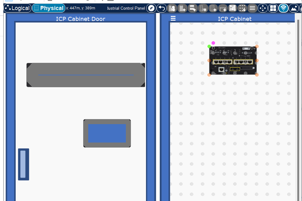
Once the mouse button is released, the item is snapped to its final position so that the item is aligned with the background dot-grid. Device items also have snapping points placed around their perimeter, in addition to the green one. These are the possible snapping points. The green dot represents the currently selected snapping point for the item. To change this point to a different one, press the Tab key while you are still dragging the item. With each Tab press, the green snapping point moves from its current dot to the next orange dot. This allows for 6 possible ways to snap-align the item to the underlying grid.
DIN rails (DIN) and Wire Conduits (WIC)
These items are specific to ICP. They are available for placement using the menu accessible via the top-left button on the cabinet frame. It looks like so:
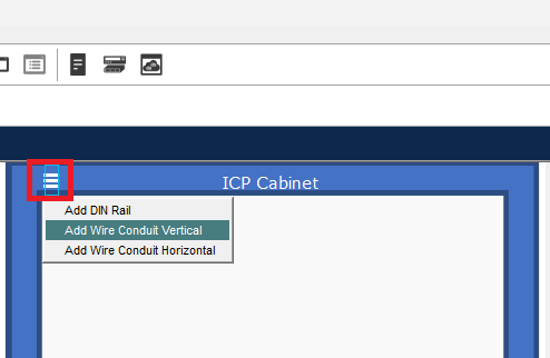
DIN rails come in a horizontal variety, while WIC can also be vertical. These items can only be placed inside the cabinet portion of the ICP.
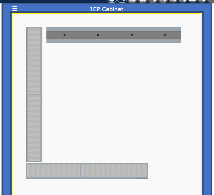
The basics of placing and positioning these items are similar to how device items are placed, as described in the previous section.
DIN and WIC multi-segment strips
These items are available as short sections. However, these sections can be connected/snapped together into longer strips using the same snapping mechanism described above. Each WIC will display its own target snapping dots. If a WIC of similar orientation is snapped to one of these, the result is a longer strip of WIC. Next time the user drags either of these segments, they will move as a unit. Once such a multi-segment strip is formed, it can be split back apart if dragging any sub-segment WIC begins with the Control key held down (Ctrl+Drag). This will separate the sub-segment under the mouse from the other segments it is connected to.
DIN rails are subject to the same behavior.
DIN-mounted devices
Just as we can connect DIN and WIC items into longer strips, the same mechanism is used when mounting device items on DIN rail strips. That is, when a device item is being dragged, DIN items will display their target/mounting dots to which a device item can be snapped. Once a device item is snapped to one of these target dots on a DIN rail, next time you drag either the DIN rail or any of the devices attached to it, the whole assembly will be dragged as a single unit. Disconnection of a device item from its DIN rail is accomplished by Ctrl-Drag, similar to how we split apart multi-segment DIN and WIC strips.
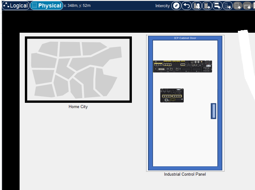
ICP Workspace Mode
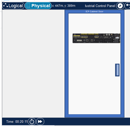
On the workspace, the ICP is represented by an icon, similar to other physical containers. In addition to this, if a user Shift-Clicks the ICP icon on the workspace, they will trigger the ICP workspace view. This is simply a closed-door version of the ICP. Any interactive items mounted on the door are interactive in this mode. The items cannot be edited when this view is active. Clicking anywhere on the ICP door background will enter the ICP. Dragging it by applying a mouse drag anywhere on its background will move it around the workspace. By clicking on the door handle, one would enter the ICP and, at the same time, exit ICP Workspace Mode, such that it will be represented on the workspace again by its icon once the user exits the ICP back to the workspace. By Shift-Clicking on the door handle, one would toggle the ICP from the workspace view back to its icon view.
Here’s what it looks like
Cabling inside ICP
This is no different from how devices are cabled together inside Wiring Closets. As a note, Wire Conduits (WIC) do not play any part in cabling and wiring inside the ICP at this time; they rather serve a purely aesthetic purpose to maintain resemblance to real-world ICPs.