Parallel Redundancy Protocol (PRP)
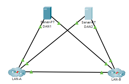
PRP uses the end nodes to implement redundancy, instead of network elements, by connecting two network interfaces to two independent, disjointed, parallel networks (LAN-A and LAN-B). These end nodes are Dual Attached Node (DAN). PRP is a layer 2 protocol.
How PRP Works:
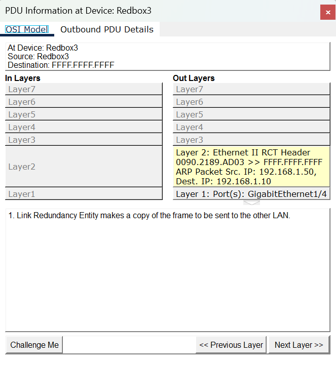
- The DAN sends two packets simultaneously through its two network interfaces to the destination node.
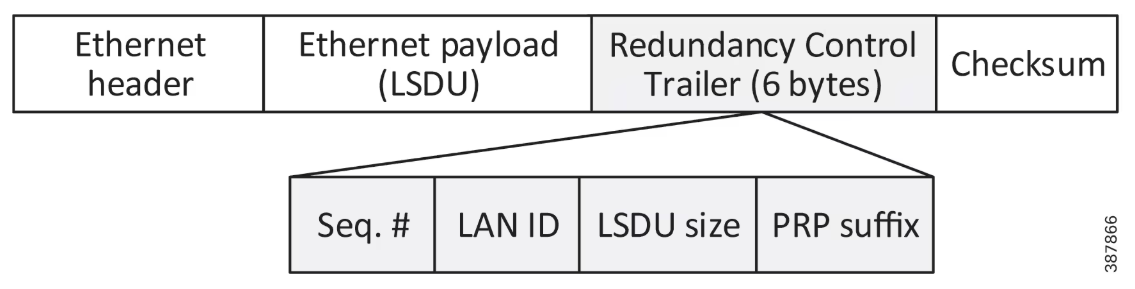
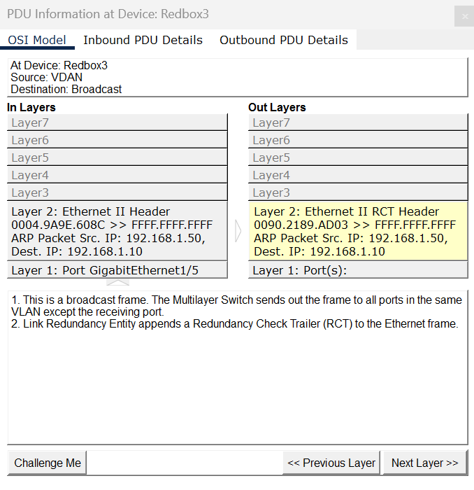
- A redundancy control trailer (RCT), which includes a sequence number, is added to each frame to help the destination node distinguish between duplicate packets.
- When the destination DAN receives the first packet successfully, it removes the RCT and consumes the packet.
- If the second packet arrives successfully, it is discarded.
- If a failure occurs in one of the paths, traffic continues to flow over the other path uninterrupted, and zero recovery time is required.
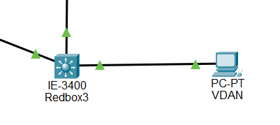
A simple network topology with DANs