Precision Time Protocol (PTP)
PTP is a layer 2 protocol. To simulate a ptp network, users need to configure at least a ptp slave clock and a ptp master clock.
PTP Slave Clock
End Devices: Users can configure PTP slave clocks on end devices by enabling it on the Config tab in device dialog.
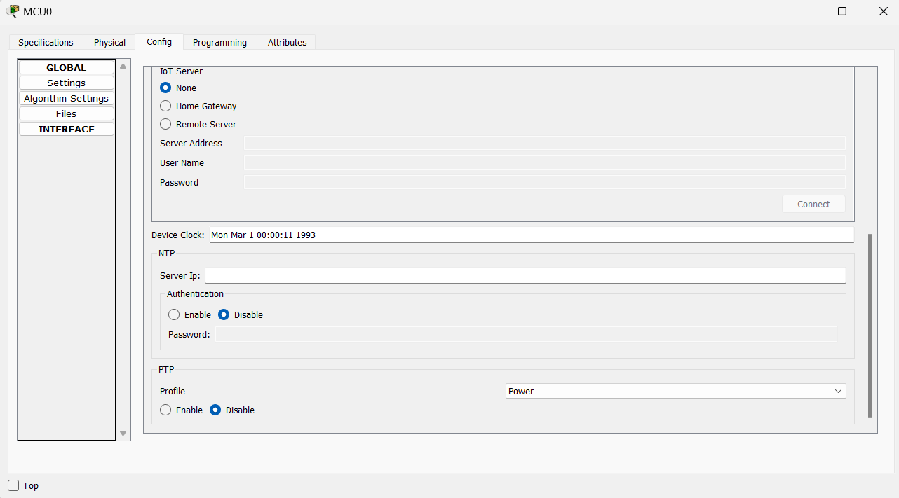
Device Clock reflects the time of the end device. This time will be updated when the device gets time from PTP master clock. If NTP is also running, NTP takes precedence over PTP.
Cisco Devices (IR-8340, IE-9320): IR-8340 and IE-9320 only support power and power-2017 profile.
Users can configure these cisco devices to be ptp slave clock with the following configurations:
- IR-8340: configure the device to be an ordinary clock
ptp clock ordinary domain 0 profile power/power-2017
clock-portslave
transport ethernet multicast interface - IR8340, IE-9320: configure the device to be a boundary clock with low priority1 (highest number means lowest priority)
    ptp clock boundary domain 0 profile power/power-2017

    priority1 255

    clock-port

    transport ethernet multicast interface
PTP Master Clock
Users can configure master clocks on IR-8340 and IE-9320 by making them boundary clocks with high priority (lowest number means highest priority).
    ptp clock boundary domain0 profile power/power-2017

    priority1 1

    clock-port

    transport ethernet multicast interface
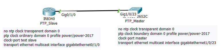
Simple PTP Topology
This is a simple PTP topology that consists of a ptp slave and ptp master with the required configurations.
Commands to Verify That PTP Is Working
Use the commands “show ptp lan clock”, “show ptp lan port”, “show ptp clock dataset parent” to view the ptp clock time and clock state on both slave and master devices.
PTP_Slave
Router#show ptp lan clock

  PTP CLOCK INFO : Clock Id : 0

  PTP Device Type: ORDINARY CLOCK

  PTP Device Profile: POWER

  Clock Identity: 0x00:60:70:FF:FE:E6:E9:00

  Clock Domain: 0

  Number of PTP ports: 1

  PTP Packet priority: 4

  Time Transfer : LINEAR

  Priority1: 128

  Priority2: 128

  Clock Quality:

        Class: 248

        Accuracy: Unknown

        Offset (log variance): N/A

  Offset From Master(ns): -2000128

  Mean Path Delay(ns): 0

  Steps Removed: 1

  Local clock time: 2011-03-30  01:41:38 UTC

Router#


Router#show ptp lan port

 PTP PORT DATASET: GigabitEthernet0/1/0

   Port identity: clock identity: 0x00:60:70:FF:FE:E6:E9:00

   Port identity: port number: 3

   PTP version: 2

   Port state: SLAVE

   Delay request interval(log mean): 5

   Announce receipt time out: 3

   Peer mean path delay(ns): 0

   Announce interval(log mean): 1

   Sync interval(log mean): 0

   Delay Mechanism: Peer to Peer

   Peer delay request interval(log mean): 0

   Sync fault limit: 10000

   Rogue master block: FALSE

   Ingress phy latency: 725

   Egress phy latency: 0
PTP_Master
Switch#show ptp lan clock

  PTP CLOCK INFO : Clock Id : 0

  PTP Device Type: BOUNDARY CLOCK

  PTP Device Profile: POWER

  Clock Identity: 0x00:D0:BC:FF:FE:94:92:00

  Clock Domain: 0

  Number of PTP ports: 1

  PTP Packet priority: 4

  Time Transfer : LINEAR

  Priority1: 128

  Priority2: 128

  Clock Quality:

        Class: 248

        Accuracy: Unknown

        Offset (log variance): N/A

  Offset From Master(ns): 0

  Mean Path Delay(ns): 0

  Steps Removed: 0

  Local clock time: 2011-03-30  01:41:38 UTC


Switch#show ptp lan port

 PTP PORT DATASET: GigabitEthernet1/0/23

   Port identity: clock identity: 0x00:D0:BC:FF:FE:94:92:00

   Port identity: port number: 23

   PTP version: 2

   Port state: MASTER

   Delay request interval(log mean): 5

   Announce receipt time out: 3

   Peer mean path delay(ns): 0

   Announce interval(log mean): 1

   Sync interval(log mean): 0

   Delay Mechanism: Peer to Peer

   Peer delay request interval(log mean): 0

   Sync fault limit: 10000

   Rogue master block: FALSE

   Ingress phy latency: 725

   Egress phy latency: 0


Switch#show ptp clock dataset parent


CLOCK [Boundary Clock, domain 0]


  Profile: Power


  Parent Clock Identity: 0x00:D0:BC:FF:FE:94:92:00

  Parent Port Number: 0

  Parent Stats: No

  Observed Parent Offset (log variance): 0

  Observed Parent Clock Phase Change Rate: 0


  Grandmaster Clock:

    Identity: 0x00:D0:BC:FF:FE:94:92:00

    Priority1: 128

    Priority2: 128

    Clock Quality:

        Class: 248

        Accuracy: Unknown

        Offset (log variance): N/A
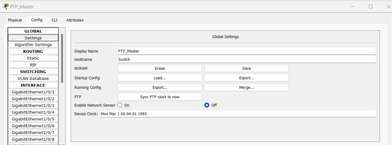
PTP GrandMaster Clock Functionality
PT does not have a dedicated grandmaster clock device from which ptp master clock can get the time from. We added an option to sync PTP clock to your system time on IR-8340 and IE-9320. This will substitute the functionality of the grandmaster clock. When users click on the button “Sync PTP clock to now”, ptp clock will be adjusted to be the same as users’ system clock. Users can use the command “show ptp lan clock” to verify. Device Clock will not be changed.
PTP Transparent Clock
PT also supports Transparent Clock which can measures the local link delays using the peer delay mechanism, determine the residence time and make corrections to sync messages. Add a ptp transparent clock between a ptp slave and a ptp master with the following configurations for a working ptp network.
IE-2000 only supports default profile.
IE-2000 won’t work with IE-8340 and IE-9320 to form a ptp network because of the mismatching profile.
Examples
| Sample File | Description |
|---|---|
ptp_IR8340.pkt |
This file demonstrates a PTP network featuring both boundary clocks and ordinary clocks. The boundary clock assumes the role of the master clock based on its clock ID. |
ptp_ot_network.pkt |
This file demonstrates how to use the 'Sync PTP Clock to Now' feature on the master clock to synchronize all OT devices to its time in the PTP network. |
ptp_power2017Profile.pkt |
This file demonstrates a PTP network that contains transparent clocks running in the Power-2017 profile, as well as ordinary and boundary clocks running in the Power profile. Users can observe traffic in simulation mode to see the differences in packet formats between the two profiles. |
Current Modeling Limitations
- The new PTP feature added in Packet Tracer only support power-2017 profile.
- PTP power-2017 profile does not support dynamic time inaccuracy reporting, short Grandmaster Identity , local time and IRIG-B replacement.
- The default PTP domain number is 0 and Packet Tracer only supports 1 domain in the network.
- Clock accuracy is only up to microseconds
- No support for vlan tagging