The Physical Workspace
The Physical Workspace
The purpose of the Physical Workspace is to give a physical dimension to your logical network topology. It gives you a sense of scale and placement (how your network might look in a real environment).
The Physical Workspace is divided into four main containers to reflect the physical scale of four environments: Intercity, City, Building, and Wiring Closet. The Intercity is the largest environment. It can contain many cities. Each city can contain many buildings. Finally, each building can contain many wiring closets. The wiring closet provides a view that is different from the other three views. This is where you actually see the devices that were created in the Logical Workspace; positioned in networking racks and on tables. The three other containers provide thumbnail views of their layouts as the next level icons. This is the default arrangement in the Physical Workspace. The devices in the wiring closet can be moved to any of the containers. When the devices are moved to another container, they revert to the icons used in Logical Workspace, although those can be customized (covered under Customization) to any graphic you would like to use.
In addition to the above mentioned main physical containers, users can create Generic Containers. These can contain any other containers provided they fit inside one another based on their volume. Other restrictions on why one container may not be possible to move into another is based on container type. For instance, a City can not be moved inside a Building regardless of the relative volumes of the two.
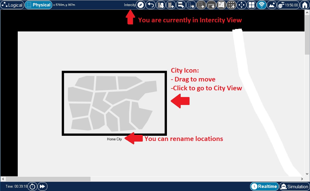
When you first enter the Physical Workspace, the default is the Intercity view (or "map").
By default, the Intercity contains one city object called "Home City." You can click and drag the City icon to move it around in the intercity map. You can also simply click on the City icon to change focus to the map of that city.

The Home City also contains one default building object called "Corporate Office." This building, like the Home City object in Intercity view, can be moved anywhere around the city. Click on the Building icon to change focus to the interior selected building. All buildings are limited to one floor. From the City view, you can also return to the Intercity environment by clicking on the Back button twice in the Physical Workspace Bar.

The Corporate Office contains one default wiring closet called "Main Wiring Closet." Click its icon to view its contents. You can also return to any of the previous environments (Intercity or City) by clicking the Back button in the Physical Workspace Bar.
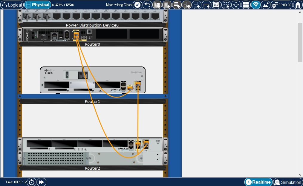
The "Main Wiring Closet" initially houses all the devices that were created in the Logical Workspace except for End Devices and Components. It neatly arranges those devices onto racks and tables so you can see where your devices physically are. The wiring closet view also shows the connected ports and the link light status of the devices in the wiring closet. If the device is clicked, its configuration window pops up just as it does in Logical Workspace. Learn how to move these devices around in the building or even the city in the "Moving Devices" section.
Devices in RackView can also be placed on a Shelf. These devices must have their power turned off and can not be connected to other devices, while they sit on a Shelf. Shelves used for storage exclusively. More than one Shelf can be added to RackView by using a button in the top toolbar. Before moving device from Rack/Table onto a Shelf, the device must be disconnected from other devices and its power must be swiched off.
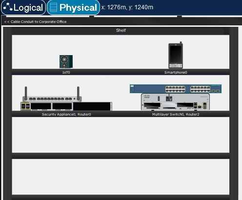
Shelf.
As shown in the above image, devices can be stacked on a Shelf; the Tables also allow stacking of the devices on top of each other. One can also place a device under the Table.
Wiring closets, buildings, and cities can all be renamed. |
Creating Devices
As mentioned earlier, Physical Workspace consists of Intercity, City, Buildings and Generic Containers. Adding devices to the Physical Workspace is the same as in Logical View. The Network Component Box is used to select devices to be added. Devices added here will also be created in Logical View. The placement in Logical View is determined by drop/click position of the device added in Physical Workspace.
To Add Devices to the current Physical Workspace view
Moving Objects
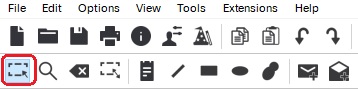
To move an object around the Physical Workspace, be sure the Select Tool is selected on the Common Tools Bar. Once the Select Tool is selected, you can left-click and drag items around the Physical Workspace.
| Physical Workspace objects can also align items when close to other objects. Click and drag on your object and move it close to the object you want to align with. Alignment lines can be enabled in Preferences, under the Interface tab. |

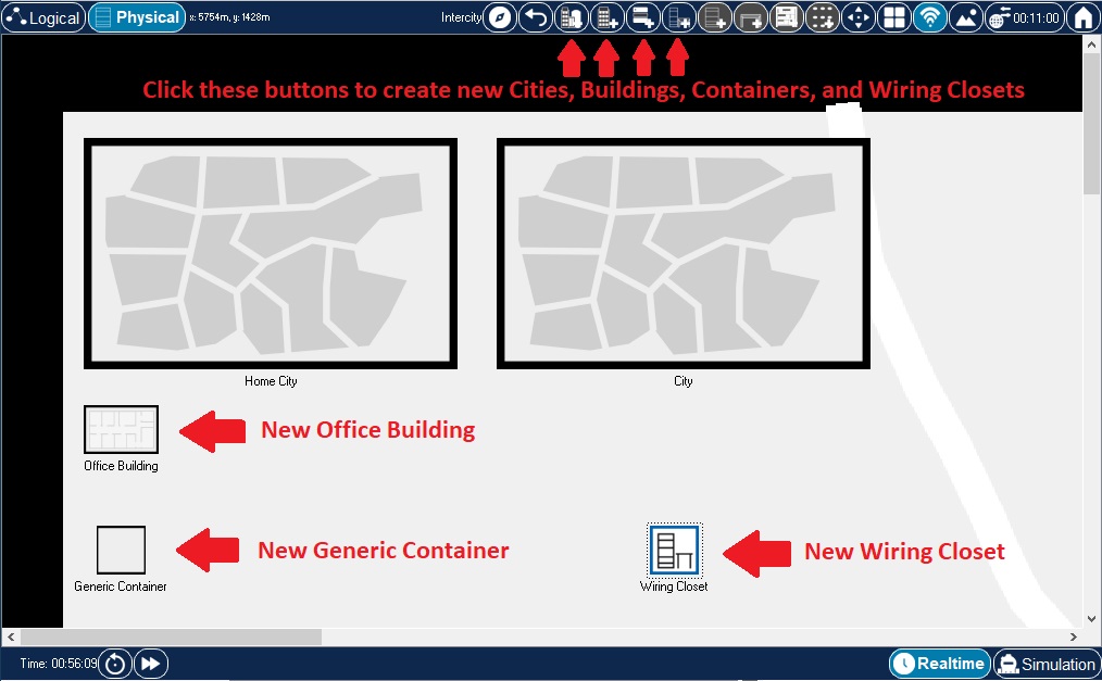
Creating New Locations
The Physical Workspace allows you to create new locations to expand your physical topology. In the Intercity environment, you can create cities with the New City button. You can place new buildings and closets directly onto the Intercity environment with the New Building and New Closet buttons. Similarly, you can create new buildings in the City environment and new closets in the Building environment. Use New Container to create new Generic Containers. To keep things simple, you should create locations according to the established hierarchy.
New cities (and buildings and closets) always initially appear on the top left corner of the workspace. To avoid confusion, you should immediately rename and move them. |
Physical Dimensions
Physical containers (generic containers, cities, buildings and closets) inherently have physical dimensions: width, length and height, measured in meters. Container's dimensions have significant effect on whether one container can be placed inside of another container. Naturally, containers of larger dimensions can not be placed inside the containers of smaller dimensions. Physical container size also affects the distance calculations inside a container, which, in turn, affects cable lengths. Customizing Icons & BG has more details on where and how to change the physical dimensions of containers.
Cable Pegboard in RackView
Pegboard is a cable storage container that is available in RackView. To add one to the current view, click a pegboard button in the top toolbar. In order to add cables to a pegboard, one would simply drag a cable from the Component Box and drop it on the pegboard. Pegboard cable slots will be highlighted during this drag and drop operation. In the next sections it will be explained how to make connections using cables from the pegboard.

Pegboard.
Making Connections
Cabling devices in Physical View is similar to that of Logical View. A variety of ways to make connections between devices in Physical workspace are given below. A singular distinctions between connections in Physical and Logical workspaces relates to the fact that in Physical every cable and wireless link are subject to physical spaces they are part of. Just like in the real world, in Physical workspace cables have length and wireless links have distance ranges associated with them. Packet Tracer allows users to take these spatial properties of network links into account when they design and test their networks. In Preferences dialog you can turn on and off the effects physical properties of cables and wireless links have on network behavior (see Enable Cable Length Effects and Show Wireless Grid options under Interface and Hide tabs respectively). When you opt to enable these cable effects, beware that moving connected devices between or within physical containers will affect physical properties of their cable and wireless links and that, in turn, can play a role on whether devices can successfully communicate with one another. In this case, any time you notice that two devices in Logical workspace do not communicate with one another, you may want to check whether the cables they are connected with do not exceed maximum cable length for the cable type used. Likewise, it might be worth checking if two wireless devices are not separated by too great a distance between them for the wireless link to be possible. Distance Measurements section has more information on this subject.
The following sections will address various ways one can connect devices in Physical workspace.
Modifying Connections
Other Features in RackView
Invoking context menu on a cable allows users to manage/un-manage the cable or change its color. In Managed state cables are rendered with the middle section of the cable hidden. In Un-managed state cables are rendered as "hanging" lines between their respective ports.
Device Context MenuAllows users to inspect front and rear sides of the device, manage/un-manage cables for all device cable connections.
Mouse Wheel ZoomZoom level in the RackView can be changed up and down using mouse wheel.
Creating Custom Devices